Final Project

Artistic Description of Work:  I have entitled my work “Auxesis”  which is from the greek meaning growth. Auxetic shapes occur in nature, specifically in cellular structure of many protein molecules. These shapes are unique in that they exhibit a negative Poisson’s ratio, meaning their lateral width increases when stretched from either end. This inverse stretching behavior mimics the movement of the chromatophore cells within the chameleon and other animals. On the skin of the chameleon, several chromatophores exists containing varying colors. These chromatophores behave as a flexible bags of color that is either stretched out to cover a large flat area or retracted back to a small, retracted point. Each chromatophore is attached to radial muscle fibers at various points along its edge controlled by a nerve fiber. When a nerve impulse is sent, it causes these muscles to contract and expand the chromatophore. When the muscles relax, the chromatophore returns to a small, compact shape, thus reducing its area and making the pigmented area shrink. This work employs shape memory polymers with fabric shaped in an auxetic shape, a chiral, to mimic the behavior of chromatophores. Shape memory polymers are materials that can recover a set shape upon heating. This recovery is due to the fact that the stiffness of the material changes above what is called the glass transition temperature, Tg. Above this temperature, the material is “rubbery” and below it the material is “flexible.” When a shape memory polymer is heated above its Tg, it can be deformed. Upon cooling, it will keep its deformed shape until heated again to a temperature above Tg.

Description of Process of the Artwork:  The artwork contains three components, the shape memory polymer, the servo motors, and the temperature sensors.  A description of the process involved making the artwork is given below:

Molding the Shape Memory Polymer (SMP):  In order to make the shape memory polymer, first a mold to cast the polymer in was made.  A mold design was drawn in SolidWorks and then the printed with the 3D printer.  The mold made from the 3D printer is given below:

Planar Tension Mold made from 3D printer using ABS plastic

Planar Tension Mold made from 3D printer using ABS plastic

This 3D printer mold was used to cast a silicon rubber mold.  To make the silicone rubber mold, Freeman V-330 Mold Making Silicone Rubber was used.  The V-330 silicone rubber components were weighed and mixed in the proper ratios. The mixture was then degassed for approximately 20 mins and poured into the 3D printer mold.  This mixture cured in the 3D printer mold for at least 16 hrs.  The silicone rubber mold is given in the picture below:

Planer Tension Silicone Rubber Mold

Planer Tension Mold made from Silicone Rubber

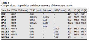
This mold was used to cast the polymer.  In order to make the polymer, three components are mixed together, these components are Jeffamine D-230, Epon 826, and Neopentyl Diglycidyl Ether (NGDE).  Jeffamine D-230 is the cross-linking agent in this mixture.  Depending on the ratios of NGDE and Jeffamine, the glass transition temperature can be adjusted.  Xie et. al. has tested various mix ratios and has given them in the table below (1):

screen-shot-2014-02-05-at-12-35-39-pm

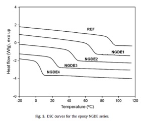
The mix ratios of concern are NGDE1-NGDE4.  Xie et. al. have also done differential scanning calorimetry (DSC) on these different mixtures to determine their Tg values.  The results of the DSC are given below (1):

screen-shot-2014-03-06-at-8-29-16-am

Therefore, from the table and DSC results a suitable mixture can be chosen depending on the desired transition temperature.  A summary of the converted mole ratios to volume ratios and Tg values for each of the mixtures is given below:

NGDE1:  4.7 ml Epon 826/2.43 ml Jeffamine/1 ml NGDE, Tg ~ 70 deg C

NGDE2:  3.14 ml Epon 826/2.43 ml Jeffamine/2.08 ml NGDE, Tg ~ 50 deg C

NGDE3:  1.57 ml Epon 826/2.43 ml Jeffamine/3.12 ml NGDE, Tg ~ 30 deg C

NGDE4:  0 ml Epon 826/2.43 ml Jeffamine/4.15 ml NGDE, Tg ~ 10 deg C

In order to make the SMP, the desired transition temperature is chosen with the associated appropriate volume ratios and the ratios are scaled to fill the silicone rubber mold.  The Epon 826 is heated at 75 deg C on a hot plate for approximately 15 minutes to increase its flow.  Then, all three components are measured and stirred together in a beaker.  The mixture is then degassed for approximately 20 minutes or until no bubbles appear.  The degass set-up is given below:

This photo is of the degassing set-up which contains a vacuum pump, a thermocouple, a hot plate, and a degauss chamber.  The thermocouple and the hot plate are used to heat the mixture, below the Tg and above room temperature, while degassing.

This photo is of the degassing set-up which contains a vacuum pump, a thermocouple, a hot plate, and a degauss chamber. The thermocouple and the hot plate are used to heat the mixture, below the Tg and above room temperature, while degassing.

After the mixture is degassed, it is poured into the silicone mold.  Then it is set in the oven to cure.  The SMP is cured 100 deg C for 1.5 hrs and then post-cured at 130 deg C for 1 hr.  A picture of the oven is given below:

The oven used to cure the SMP.

The convection oven used to cure the SMP.

After, the SMP was cured, the oven door was left open to allow the SMP to cool in mold.  It was found that if the oven door was not left open, some additional post-curing occurred which in turn affected the Tg.  A picture of the resulting SMP is given below:

SMP made using silicone planar tension mold.

SMP made using silicone planar tension mold.

Laser-Cutting the Shape Memory Polymer:  To explore different shapes that would mimic the chromatophore, the laser-cutter was used.  Through, this exploration, a chiral shape, which is an auxetic shape exhibiting a negative Poisson’s ratio, was chosen.   This idea was based on the work of Rossiter et. al.  The images below from Rossiter describe how the chiral works (2):

Contraction of chiral structures; (a) expanded and (b) compressed triangular element, (c) a single structural element at maximum extension and (d) at maximum contraction (1)

Contraction of chiral structures; (a) expanded and (b) compressed triangular element, (c) a single structural element at maximum extension and (d) at maximum contraction (2)
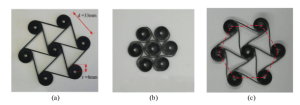
(a) As-fabricated deployed state of laser cut SMP hexachiral auxetic, (b) compressed storage state, (c) deployed structure after shape recovery (2)

(a) As-fabricated deployed state of laser cut SMP hexachiral auxetic, (b) compressed storage state, (c) deployed structure after shape recovery (2)

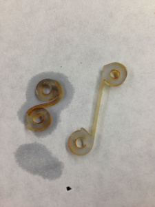
A picture of one of the chiral I created is given below:
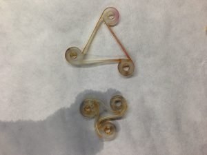
Auxetic shape memory polymer that has been compressed to its “closed” position (object on the bottom) from its “set” position (object on the top).

Auxetic shape memory polymer that has been compressed to its “closed” position (object on the bottom) from its “set” position (object on the top).

I went through several iterations of the chiral shape, in order to get the legs of the chiral thick enough as to not break easily.  Also, I found that at a low Tg, the laser-cutter did not perform well, and the polymer resulted in a gummy polymer that was useless.  Furthermore, the polymer did better when it was taped prior and frozen prior to being cut. The final chiral shape chosen was the six sided-chiral shape.

Incorporating Color Into the Shape Memory Polymer:  Color was incorporated into the SMP using Solar Color Dust and Castin’ Craft Dye.  Solar Color Dust changes from color to clear around 30 deg C.  There were four Solar Color Dust colors to choose from:  Rubine Red, Green, Blue, Magenta.  In order to incorporate the Solar Color Dust, the dust was sonicated into the Jeffamine D-230 prior to the mixture with NGDE and Epon 826.  The sonication proved the best method to incorporate the dust, since stirring the dust left some “weak” areas in the final product.  Weak in the sense that the dust was not evenly distributed from the stirring.  Sonication uses shear force to distribute particles in a solution, therefore creating a more even distribution of particles.  For the final project, four colors combinations were tried:

1.  Rubine Red Solar Color Dust/Blue Dye

2.  Blue Solar Color Dust/Yellow Dye

3.  Magenta Solar Color Dust/Green Dye

4.  Green Solar Color Dust/Black Dye

Also, fabric was glued onto the inside of the polymer to represent the color sac aspect of the chromatophore.  The fabric color was chosen to correspond with dye color of the polymer.  A picture of the colored chorals is given below:

The colored shape memory chirals with fabric incorporated.

The colored shape memory chirals with fabric incorporated.

Some of the dyes, the green dye and the black dye, did not show up when heat was applied.  However, the yellow dye and the blue dye do show when heat is applied.  The color changes in the chirals are seen below:

This chiral changes from blue to yellow.  The blue and yellow colors are depicted.

This chiral changes from blue to yellow. The blue and yellow colors are depicted.

This chiral changes from purple to blue.  The purple and blue colors are depicted.

This chiral changes from purple to blue. The purple and blue colors are depicted.

Heating/Moving the Shape Memory Polymer:  In order to utilize the shape memory aspects of the polymer, heating, cooling, and mechanical deformation need to be employed.  The thermomechanical cycle is as follows:

1.  The polymer is heated to approximately 20 deg C above the Tg.

2.  At this temperature, the polymer is mechanically deformed by applying a load.

3.  While the load is applied, the polymer is cooled rapidly to a temperature approximately 20 deg C below the Tg.  This cooling sets its new deformed shape.

4.  When the polymer is heated again, the original set shape is obtained.

For this aspect of the piece, the main difficulty was obtaining a flexible enough polymer and heating it consistently.  Several formulations to adjust the Tg were experimented with.  However, a Tg much higher than room temperature, above 50 deg C proved the ideal Tg.  Also, several options in regards to heating the polymer were tried.  These options included:  heating with shape memory alloy, heating with a hair dryer, heating with a heating pad, and adding conductive carbon black to the polymer.  The hair dryer and the heating pad proved the best means to heat the polymer.  Of these two, the hair dryer was chosen because the convection heating was faster than the heating pad and it allowed for interactivity with the audience.

In order to mechanically deform the SMP several options were explored including using shape memory alloys, using a gear system, using various servo motors.  The shape memory alloys did not provide enough tension to pull the chiral together.  Of the other two options, the servo motor with a 6-horn arm provided the best solution to the problem.  However, the servo did pose issues in regards to attachment to the canvas background.  The placement of the linkage attachment was crucial.  The 180 deg servo was initially tried.  The 180 deg rotation did provide enough tension to pull the polymer inwards.  The full rotation servo motor, however did provide the required tension.  A video of the shape memory polymer closing upon being heated is given here:  http://youtu.be/qsI6kRHkyr0.

Temperature Sensing the Shape Memory Polymer:  The temperature of the SMP was detected using the lilypad temperature sensor.  The main concern with the temperature sensing, was the location and making sure that the polymer was at a consistent temperature throughout, so it would be flexible.  In order to do this task, the time the temperature sensor read the output was tracked.  The code used to calibrate the temperature sensor is given here:  Temperature_Calibration_Code

Description of the Physical Aspects of the Piece:  The piece is made of canvas with SMP as well as other fabric.  The additional fabric was used to incorporate texture and additional color depth into the work.  This fabric is a representation of the octopus’s skin in that it can manipulate texture as well as color.  The movement of the polymers is based on the temperature sensing.  The temperature sensor and corresponding movement indicates the animal’s response behavior to its environment.  As was said earlier, the fabric inside the polymer depicts the bag of color for the polymer.  On the back of the canvas, the arduino, servo motors, and temperature sensors are attached.  A picture of the front and back of the canvas is given below:

photo 1

This picture is of the back of the artwork.

This picture is of the front of the artwork.

This picture is of the front of the artwork.

The code for this project is given here:  Final_Project_Code

A video of the project working is given here:  http://youtu.be/NFLGhkl_17g

The piece works based on temperature sensing.  The polymer is heated using a hair dryer.  When the temperature senses the appropriate temperature above the Tg is reached, then the servo motor turns to mechanically deform the polymer, close the chiral shape.  When the viewer sees the polymer close, then he or she can turn off the hair dryer.  The servo motor stays in this position until the temperature senses that the polymer is cooled to set the shape.  The polymer is cooled using compressed air.  The viewer can spray compressed air onto the polymer and can sense when it is cool by the color change and the fact that the motor will turn to release the polymer.  Once the mechanical load on the polymer is released, the polymer will hold the set shape until it is heated again.  When it is heated again, the polymer will return to its set shape.  Once this heating is done, and the product cools down again the shape memory polymer is ready to repeat the cycle.

If I was given more time, I would have liked to incorporate a larger number of polymers into the work.  However, there was some issues with the mold warping after a short usage, so I was unable to make more polymers.  Also, I would liked to have obtained a method mechanically closing the polymers without the wire being visible.

Future Work:  For future work, I would like to do the following:

1.  Perform DSC measurements on the polymer with incorporated powder to see if the powder and dye change the Tg value.

2.  Explore larger networks of auxetic shapes.

References:

1.  Xie, T., Roussea, K., Facile tailoring of thermal transition temperatures of epoxy shape memory polymers, Polymers, 2009, 50, 1852-1856.

2.  Rossiter, J. et. al., Shape Memory Polymer Hexachiral Structures with Tunable Stiffness.  Smart Materials and Structures. 23 (2014).

Final Project: Current Work Update

Current Work for Chiral Spacing

Current Work for Chiral Spacing

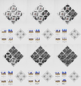
I have currently been working on the set-up of the chiral structure.  The picture above depicts the possible set-up of the structure.  The outer part of the chirals contains the color at room temperature.  The inner part of the chirals contains the fabric color which corresponds to the color above 30 C.  I have given below some of the color change pictures of the chiral structures.

This chiral changes from purple to blue.  The purple and blue colors are depicted.

This chiral changes from purple to blue. The purple and blue colors are depicted.

This chiral changes from blue to yellow.  The blue and yellow colors are depicted.

This chiral changes from blue to yellow. The blue and yellow colors are depicted.

I have added pictures of the chirals with fabric incorporated.  These photos are given below.

This chiral has rubine red powder with blue dye and blue fabric super glued to the back of it.

This chiral has rubine red powder with blue dye and blue fabric super glued to the back of it.

This chiral has blue powder with yellow dye and yellow fabric super glued to the back of it.

This chiral has blue powder with yellow dye and yellow fabric super glued to the back of it.

Current Work: Final Project

My final project incorporates two aspects of the chromatophore:  shape change and color change.  The current work in relation to each is given here.

Color Change Work:

The color change is created in the polymers by incorporating a product called “Solar Color   Dust” (1).  This thermochromatic powder is sonicated into the polymer.  The powder changes color at 30 deg C.  The dust goes from colored to white.  Also, I have incorporated Castin’ Craft resin dyes in the material (2).  This dye changes the color of the polymer from clear to the dye color.  I have made a polymer with thermochromatic powder and dye.  Therefore, when the polymer is heated above 30 deg C, the powder becomes white and the color of the dye show through.  An example of this type of system is given below:

Shape memory polymer with Rubine Red Solar Color Dust and Blue Casting Craft Dye.  A nichrome wire has been incorporated into the polymer.  Here, the wire has been heated.  As you can see, the heat concentration has caused the powder to become white and allowed the blue dye to show through.

Shape memory polymer with Rubine Red Solar Color Dust and Blue Casting Craft Dye. A nichrome wire has been incorporated into the polymer. Here, the wire has been heated. As you can see, the heat concentration has caused the powder to become white and allowed the blue dye to show through.

Possible combinations of thremochromatic powder and dyes that could be used in this project are given below:

Solar Color Dust Color: Casting Craft Dye Color: Color of Polymer at 25 C: Color of Polymer at 30 C:
Rubine Red Blue Purple Blue
Sky Blue Green Cyan Green
Magenta Yellow Red Yellow
Green Red Yellow Red

Shape Change Work:

In order to get the shape change, a “chiral” or “auxetic” shape is being used for experimentation.  These shapes are unique in the fact that their Poisson’s ratio is negative, meaning as the structure flexes when stretched (3).  A photo of an auxetic shape memory polymer is seen below:

Auxetic shape memory polymer that has been compressed to its "closed" position (object on the bottom) from its "set" position (object on the top).

Auxetic shape memory polymer that has been compressed to its “closed” position (object on the bottom) from its “set” position (object on the top).  (Note:  The cross-sectional area is 0.3 in^2 and the height is 3 mm.  The volume is 0.03 in^3.)

Smaller movement to practice the auxetic shape.  Note:  The cross-sectional area here is 0.17 in^2 and the height is 3mm.

Smaller movement to practice the auxetic shape.  (Note: The cross-sectional area here is 0.17 in^2 and the height is 3mm.  Also, the perimeter is 4.17 in.  The volume is 0.2 in^3.)

A video of this material changing shape is seen here:  https://www.youtube.com/watch?v=nZGNkn1s4F0&feature=youtu.be.

In order to create change through electrical heating, the specific heat of the material, glass transition temperature and power requirements should be known.  The energy required to heat the substance is given by:

E = P*t = m*Cp*(Tf-T0)

where P is the power in Watts, t is the time in seconds, m is the mass in kg, Cp is the specific heat in kJ/(kg*K), and Tf and T0 are the final and initial temperatures in K.  The specific heat of this material is estimated based on Lelieveld’s values (4).  Her data is given in the photo below:

Specific heat data of smp (4)

Specific heat data of smp (4)

The specific heat is estimated by using the value for 95 deg C.  The power is found by calculating the mass.  The density of the material is approximately 1 g/cm^3.  For the auxetic shape, the mass and corresponding energy is given as:

m = (1 g/cm^3)*(0.03 in^3)*((2.54 cm/1 in)^3) = .491612 g

E = 0.49 g(1900 J/kg/K)*(1 kg/1000g)*(90-25)K= 60 J

This power is represented as:

P = V^2/R = E/t

where V is the voltage in volts, R is the resistance in ohms, and t is the time in seconds.  The power is found to be:

15 secs:  P = 60 J/30 sec = 4.0 W

30 secs:  P = 60 J/30 sec = 2.0 W

60 secs:  P = 60 J/60 sec =  1.1 W

The resistance of the material can be calculated based on the resistivity:

R = rho*l/A

with rho as the resistivity in ohm/m, l as the length, and A as the cross-sectional area.

The calculations for the project are given here:  SMA_SMP_Calculations

References:

1.  http://www.solarcolordust.com/Site/Thermal_Shop.html

2.  http://shop.hobbylobby.com/products/green-transparent-resin-dye-761650/

3.  Prall D, Lakes R.  Properties of a chiral honeycomb with Poisson’s ratio -1.  Int. J. Mech. Sci.  1996;39:305-314.

4.  Lelieveld, C.  Smart Materials for the Realization of an Adaptive Building Component.  Thesis, TU Delft.  2013.


Project 3:

Premise:  Create a model of a fantasy artwork you describe in your blog.  The model should use at least two motors.

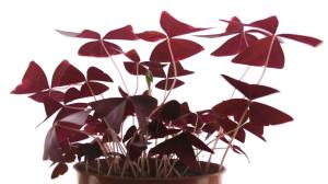
Description of Fantasy Artwork:   This artwork utilizes the concept of biomimcry of the plants that respond to external stimulus.  An example is the oxalis triangularis plant.  This plant produces a mechanical response with changes in diffuse light levels.  This movement is described as nastic and happens due to changes in osmotic pressure (1).  A video of the plant movement is given here:  http://amirshahrokhi.christopherconnock.com/2011/01/18/43/.

Oxalis Triangularis Plant

Oxalis Triangularis Plant

The purpose of the artwork is to create an interactive plant that response to a stimulus.  A work designed by Christopher Connock uses the Oxalis Triangularis plant as a model to create an interactive artwork.  A picture of his work is given below:

Interactive Art Piece Inspired by Oxalis Plant by Christopher Connock (2)

Interactive Art Piece Inspired by Oxalis Plant by Christopher Connock (2)

Also, a video of his work is given in Reference 2.  Another artist, Akira Nakayasu of Japan, has designed a similar plant artwork.  This robot is called “Plant” and it is inspired by blowing grass in the wind.  This plant responds to hand movement, and each of its leaves are controlled by shape memory alloy actuators.

"Plant" by Akira Nakayasu

“Plant” by Akira Nakayasu (3)

Another example of a plant that response to human motion is given here:  http://vimeo.com/57669812.  This video is of a dancing flower that responds to hand movement.  The flower is given below:

Interactive flower called "Dance with Us"

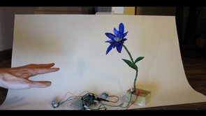
Interactive flower called “Dance with Us” (4)

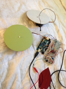
Model of Artwork:  For this artwork, the interactive plant is made from sensors and motors.  A trimpot is used along with a servo motor.  The trimpot indicates the direction of the person near the plant.  When the trimpot reading changes, the plant tilts towards the observer.  The switch indicates the water pressure in the plant.  When the switch changes, shape memory alloy moves the leaf portion of the plant.  The light sensor indicates the level of light in the room.  This sensor is connected to a stepper motor.  The motor turns based on the light level in the room.  When the light is at a higher level it turns one direction, and at a lower level it turn in another direction.  A picture of the model of the artwork is given below:

photo

The code for the project is given here:  Program_3.

References:

1.  http://amirshahrokhi.christopherconnock.com/2011/01/18/43/

2.  http://www.christopherconnock.com/project/yale/activepassive/

3.  http://www.greendiary.com/interactive-robotic-plant-reacts-to-hand-movement.html

4.  http://vimeo.com/57669812

5.  http://www.instructables.com/id/Introduction-27/

Final Project Idea

For my final project, I would like to keep with the biomimicry concept.  Specifically, I would like to focus on mimicking the behavior of chromatophores that appear in chameleons and other animals.  In these animals, their skin actually contains several chromatophores cells of varying colors.  Each chromatophore is surrounded by a circular muscle that can constrict or expand.  When the muscle constricts, pigment goes to the top of the chromatophore and the cell becomes a wide, flat disc.  Upon relaxation, the cell is a small spot, which is difficult to detect.  The color of the body is based on which pigments are being constricted at a certain time.  Below are two images that represent what is happening:

Muscle fibers expand and contract the chromatophore (1)

As different patches expand and contract, the skin of the squid changes color

As different patches expand and contract, the skin of the squid changes color (1)

Also, this video of the octopus in camouflage mode is really impressive, and it explains a little more about chromatophores:  http://phys.org/news/2013-05-chameleons-creatures-colour.html.  This video shows that in octopus, the can mimic its environment although it is color blind.  This mimicry occurs due to chromatophore’s action of only 3 colors with reflectors.  By using these three colors and reflectors, the variety of patterns can be created to camouflage.

For the project, I want to utilize shape memory material and create and interactive artwork that has both shape and color change.  Shape memory materials exhibit shape change based on a certain transition temperature in which chemical structure change within the material occurs.  For shape memory alloys, this temperature is the transition from Austenite structure to a Martensite structure.  For shape memory polymers, this temperature is the glass transition temperature where the structure goes from a rubbery to a glassy phase.  As of now, I would like to create this artwork as a “living skin”.

lotus7-0

a19c78f19c80fea740628284c37cb567

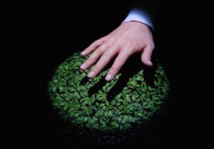
The lotus dome as an example of a living skin (2)


Also, I would like to use shape memory polymers.  Shape memory polymers have an advantage in that I can cast them into any shape using 3D printing.  I have successfully been able to create color change using Solar Color Dust (3).  This dust is an encapsulated powder that can be easily incorporated into the matrix and cause color change based on temperature.

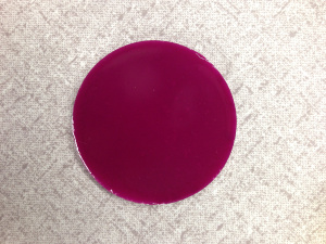
Shape Memory Polymer with Solar Color Dust

Shape Memory Polymer with Solar Color Dust

Also, the shape memory polymer provides an advantage in that the glass transition temperature can be changed by adjusting the chemical ratios within the material make-up.  I am working on doing some more experimentation with this color changing dyes, as well as patterns.

For this project, one major drawback is finding the appropriate method of incorporating a heating element into the polymer material, whether the heating element be a shape memory alloy or wire, for example, nichrome wire.  The heating element needs to be cast while the polymer is being cast, meaning it needs to be well anchored and be able to withstand 130 deg C.

The final result I desire is to incorporate shape and color through use of sensors or physical touch.  Therefore, the artwork mimic’s these animals’ response to the environment in that its pattern indicates mood or defense or attraction for a mate.  This work could be interesting in technical applications.  For example, shape memory polymer materials are being studied to create optimal wing geometry throughout the entire flight by being able to adjust its shape.  Blending shape adjustment and color would be of interest to defense applications where camouflage and optimal performance is needed.

References:

1.   http://ca-seafood.ucdavis.edu/squid/squidcol.htm

2.  http://www.emptykingdom.com/featured/lotus-dome/

3.  http://www.solarcolordust.com/Site/Welcome.html

Project 2:

Premise:  Create a model of a fantasy artwork you describe in your blog.  Your artwork should accept and display text from your Arduino monitor on your computer.  It should also use at least two sensors and two led displays.  Consider using the numeric or bar graph displays.

Description of Fantasy Artwork:  This artwork is described as a “living skin”.  It would be an example of biomimictry.  This “skin” is a roof that serves as a barrier between the interior and exterior of the building.  The skin moves based on the incorporation of a shape memory polymer system.  This movement change is based on two things:  first the amount of light outside, and then your indicated mood.  Based on the amount of light and your indicated mood the “skin” moves to adjust the lighting on the inside of the building to create a better environment, which hopefully in turn will increase the person’s mood.  Also, the artwork has the ability to receive encouraging messages from other users and project these messages onto the floor of the building through the use of a laser.

Some examples of living skin are given below:

Living Architecture inspired by Seasonal Affected Disorder (SAD) using hybrid shape memory tectonic system

Living Architecture inspired by Seasonal Affected Disorder (SAD) using hybrid shape memory tectonic system (1)

A building envisioned for China utilizing a living skin. (2)

A building envisioned for China utilizing a living skin (2)

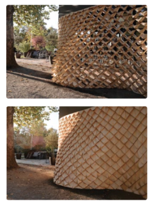
This wall is made from maple veneer and uses orthotropic material properties to create a response to moisture (3)

This wall is made from maple veneer and uses orthotropic material properties to create a response to moisture (3)

Model of Artwork:  The seven segment numerical graph receives data from the serial input and displays the character that it receives.  This display represents the messages that the other users can send to encourage the person.

The photocell receives input as to the light currently available in the room.  The led receives input from the user through the trimpot as to his or her current mood.  The mood color is displayed on the led.  The colors in order from increasing happiness:  blue, cyan, green, magenta, and yellow.  The output of the 10 segment bar graph indicates how much light is being utilized by the living skin to create the lighting to increase the person mood level.

A picture of the project set-up is given below.  Also, a video demonstration of the project can be found here:  http://www.youtube.com/watch?v=SV1bqPcqh-M&feature=youtu.be.

Project set-up

The code is given here:  Project_2

References:

1.  http://www.elaineyanlingng.com/?page_id=19

2.  http://bleuscape.com.au/blog/habitat-2020-future-smart-living-architecture/

3.  http://onlinelibrary.wiley.com/doi/10.1002/ad.1379/abstract

Project 1

Premise:  The purpose of this project is to create a model of a fantasy artwork you describe in your Blog.  For the analog inputs substitute voltage divider sensors, and for the analog outputs use PWM driven LEDs.

Description of Fantasy Artwork:  For this first project, I would like to build an arrangement using pressure sensing artwork.  More specifically, I would like to create an artwork that utilizes that replicates the biological photonic system within the “bastard hogberry” plant.  The plant itself uses its color changing to draw birds for scattering its seed.  This plant changes its color to mimic a plant of similar structure that these birds rely on for nutrients.  The change in color of the plant is due to the structural layering of cells within the seed coat.  Vukusic and his associates state that the upper cells in the seed’s skin contain a curved, repeating pattern, which creates color through the interference of light waves (1).

Image

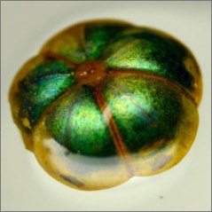
The “bastard hogberry” plant (1).

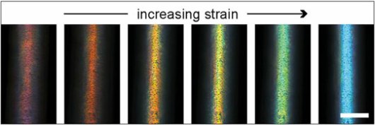
This team at Harvard has used this plant’s curved layered achitecture to inspire a multi-layed fiber.  The figure below depicts the fiber color change in relation to increasing stretch that this group created.

Image

The photonic fibers are made by wrapping muliple layers of polymer around a glass core, which is later etched away.  The thickness of the layer determines the apparent color of the fiber, which can range across the entire visible spectrum of light (1).

For my artwork, I would like to create a similar approach to the problem.  I would like to design a layered material using a significant color spectrum, meaning at minimum 5 colors or more.  More specifically, I wish to have the depth of the layer related to the amount of pressure being applied by an outside source.  Therefore, the greater the compressive stress, the more deeply the structure is affected.  Hence for light pressure, a color in the top layer is displayed and for large pressure a color on the bottom surface is displayed.  This type of material could be useful in many ways, for a practical application, it might be applied to the outer surface of a composite material to help aid in quality control.  Meaning, it could be used as a qualitative sensor to indicate the level of damage and if further scanning needs to be done.  For this artwork piece, I would like to use it as an interactive structure where the user can create his or her own painting piece through application of varying amounts of force and different locations.  An idea of something that might be created is given below:

painting

Painting created using dots (3).

Model of Artwork:  The model of the artwork represents a smaller example of the pressure sensing layers.  Three multicolored LEDs are used.  With these LEDs seven colors are possible, the possible colors are:  red, magenta, yellow, green, blue, cyan, and white.  For this representation, three layers will be represented by each of these colors starting at the bottom and going to the top:  yellow, green, blue, and cyan.  Also, darkness will be used to indicate no pressure.  Each LED will represent a different area on the artwork, and will glow the color of the pressure associated with that area.  Note that in this example point 2 represents a distance that receives the inverse pressure than point 1.  Also, the yellow LED represents only intense pressure or no pressure at point 3 in the artwork.

photo

Above is a photo of the wiring set-up.

Also, the Arduino code is given below:  Arduino_Project_1.  A demonstration video may be seen here:  http://www.youtube.com/watch?v=MkpCGhXP31s&feature=youtu.be.

What I learned was to be careful with the LEDs so as not to set-off an electrostatic charge, especially in the cold weather which might end in burning one out.

References:

1.  http://wyss.harvard.edu/viewpage/413/

2.  Kolle, Mathais, et. al., Bio-Inspired Band-Gap Tunable Elastic Optical Multilayer Fibers, Advanced Materials, 2013, 25, 2239-2245.  (http://onlinelibrary.wiley.com/doi/10.1002/adma.201203529/full)

3.  http://www.creativebloq.com/graphic-design/pointillism-examples-dot-art-11121135